1a. Het begin : Kennis, Wat is WPC, Schema's
- Wat voor
kennis op dit gebied wordt er van je
verwacht ?
Enige ervaring in het repareren van flipperkasten wordt er wel van je verwacht. Basiskennis electriciteit is gewenst maar geen noodzaak. Wel wordt er van je verwacht dat je zeer goed kunt solderen en weet hoe je met een universeelmeter moet omgaan.Wat is WPC ?
WPC betekent "Williams Pinball Controller". Het is een door Williams speciaal voor flipperkasten ontwikkelde computer die van 1990 tot 1999 werd toegepast. Technisch gesproken functioneert de WPC chip als adres decoder, handelt de I/O af die vroeger door TTL logica en 6821 PIO's werd verwerkt maar ook de systeem klok, de bewaking en de realtime klok. Er zijn meerdere generaties van de WPC (kijk bij Verschillende WPC Generaties).Heb je de schema's ?
Het bezit van een schema voor je kast is natuurlijk ideaal, soms kun je de kast echter ook repareren zonder schema. De schemaboeken en handledingen zijn meestal wel bij Wizard of Arkadia te koop.De WPC Schema boeken.
Bij enkele WPC kasten uit 1991 en eerder staan de schema's in het gewone handboek, (Gilligan's Island en ouder). Van alle andere WPC kasten, staan de schema's van de printenin de kopkast in een apart schemaboek (dus de CPU, (dot)driver, sound en fliptronics)- Voor-DCS (Funhouse tot Twilight Zone): bestelnummer 16-9473
- WPC DCS/WPC-S (Indiana Jones tot Jackbot): bestelnummer 16-9834.2
- WPC-95 (Congo tot Monster Bash): bestelnummer 16-10159.2
1b. Getting Started: Necessary Tools
- Fixing
electronic pinball games will
require a few tools. Luckily,
most are not that specialized and
are easy to get.
Non-Specialized Tools Required:
- Work Light: clamp style lamp
- Screwdrivers: small and medium size, phillips and flat head
- Nut Drivers: 1/4", 5/16", and 11/32"
- Wrenches: 3/8", 9/16", 5/8" required, other sizes suggested
- Allen Wrenches: get an assortment of American sizes
- Needle Nose Pliers
- Hemostat. Handy for holding parts and springs. Best to have both the curved and straight versions if possible.
- Right Angled Screwdriver: both phillips and flat head.
Specialized Tools Required:
These specialized electronics tools are needed. Please see http://marvin3m.com/begin for details on the basic electronics tools you will need.- Alligator clips and wire. You can buy these at Radio Shack, part number 278-001, $3.69.
- Soldering Iron.
- Rosin Core 60/40 Solder.
- De-soldering tool.
- Digital Multi-Meter (DMM).
- Logic Probe.
- Infrared Sensor. Used for determining good infrared optic LED's. Radio Shack sells these for $5.99, part number 276-1099
De benodigde schoonmaakspullen:
- Clean
'M Again, het supermiddel wat de
Flipperwinkel verkoopt.
Hiermee reinig je het speelveld zeer grondig en ook nicotineaanslag op de buitenzijde van het cabinet kun je er prima mee verwijderen, verdunnen tot wel 50% is mogelijk. Niet gebruiken op verspiegelde plastic delen en geschildere metalen delen (apron) - Superflipp of wat ouderwetser Goldcat, dit zijn daily cleaners voor het noodzakelijke onderhoud.
- Johnson's
Paste Wax, Carnauba Wax en Millwax zijn
amerikaanse producten die niet voldoen aan
onze millieuregels.
Er is een groepje mensen in NL (NFV) die persé dit spul willen hebben omdat ze het blijkbaar interessant vinden om mee te doen met rages. Niet doen, gebruik dan desnoods grootmoeders bijenwas want we kunnen hier prima zonder die usa troep. - Novus
producten zijn schuurmiddelen die bedoeld
zijn voor het poetsen van plastic ramen (Novus
Windshield Company) Het is een totaal
onzin product wat je beslist niet nodig
hebt.
Wil je toch polijsten dan haal je gewoon een bus fijne Commandant bij de automaterialenhandel.
1c. Getting Started: Parts to Have On-Hand
- When
fixing electronic pinballs, I
would highly recommend having
some parts on-hand to make things
easier and cheaper. All these
parts are available from a
pinball retailer.
Parts to have:
- #44 light bulbs: have 20 or so around. Fifty is plenty to do most games. Many people suggest using #47 bulbs instead, as they consume less power and produce less heat. In any other non-WPC game, I would say this is a good idea. But in WPC, after 15 minutes of non-play, the system automatically dims (lowers the power to) the general illumination lamps. So using #47 bulbs instead of #44 is not a big deal.
- #555 light bulbs: have 20 or so around. Fifty is plenty to do most games.
- #906 or 912 flash bulbs: have 10 or so around.
- #89 flash bulbs: have 10 or so around.
- #86 bulbs: used in Twilight Zone and Creature from the Black Lagoon only.
- #455 or #545 bulbs: blinking style bulbs. The #545 have a (#555 style) wedge base. Used only in Twilight Zone, Addams Family and No Good Gofers.
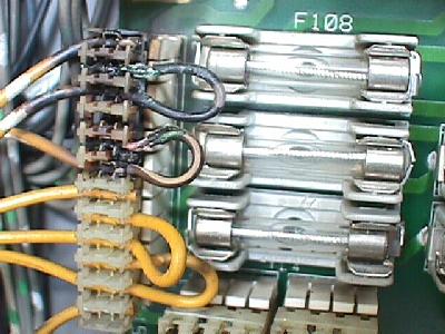
- Fuses:
I would have five of any
needed value on hand at
all times.
WPC-S and Earlier Games:
Get 250 volt fuses, not 32 volt. Radio Shack sells fuses for a decent price. Slow-blo fuses are known as MDL fuses. Fast-blo fuses are known as AGC fuses. At minimum you'll need:- 3/8 amp fast-blo (for dot matrix display)
- 3/4 amp fast-blo (used for 12 volts)
- 2 1/2 amp slo-blo (used for flippers on non-Fliptronic games)
- 3 amp slo-blo (used for solenoids, 12 volts, flippers)
- 5 amp slo-blo (used for general illumination, flash lamps, solenoids, +5 volts)
- 7 amp slo-blo (for solenoid voltages)
- 8 amp fast-blo (used for playfield lamps and line filter)
WPC-95 Games
Uses the new smaller "T" fuses, all 250 volts. Note these are not GMA fuses. GMA are similar to American fast-blo fuses. "T" fuses are more like American slow-blo fuses. WPC-95 uses nothing but "T" fuses. These fuses are smaller, about .75" long (but technically known as 5x20mm). You'll need:- T0.315 amp (audio/video board)
- T0.63 amp (driver board)
- T2.5 amp (audio/video board)
- T4.0 amp (driver board)
- T5.0 amp (driver board, line fuse)
- T6.3 amp (driver board)
- Nylon Coil Sleeves: the longer 2 3/16" length (part number 03-7066-5) are used when rebuilding flippers. The 1.75" length (part number 03-7066) are used for pop bumpers, etc. Sleeves with a lip (part number 03-7067-5) and tubing on each side (known as an "inline" sleeve) are used on the knocker, etc.
- Flipper Plunger/Link: used when rebuilding flippers (part number A-15847 or A-10656).
- Flipper Link Spacer Bushings: these small bushings go inside the flipper links (part number 02-4676).
- Flipper Coil Stops: used when rebuilding flippers (part number A-12390).
- Flipper EOS Switch: part number 03-7811 (non-Fliptronics) and SW1A-193 (1992 and later Fliptronics games).
- 1/4" Heat Shrink Tubing: this is used on the flipper pawl when rebuilding flippers.
- Shooter Spring: the short chrome spring on the outside of the shooter mechanism (part number 10-149). These rust and look like crap in short order.
- 1 1/16" Pinballs: a new pinball will make your playfield last longer.
- Leg Levelers: replace those old crummy looking leg levelers with brand new ones. 3" are used on solid state games.
- Rubber Rings: you can order game-specific ring kits with exactly the rings you need (from Pinball Resource). Don't forget to get flipper rubbers and a shooter tip.
- Transistors: keep a few TIP102, TIP107, 2N5401, 2N4403, and TIP36c around.
- Diodes: keep a few 1N4004 diodes around. If you have a WPC-95 games, keep a few P600D or 6A4 diodes around (used on the WPC-95 driver board for converting AC voltage to DC).
- Bridge Rectifiers: if you have a WPC-S or earlier game, keep a few 35 amp, 200 volt (or higher) bridge rectifiers around, with wire leads. The industry part number is MB3502W (Williams part number 5100-09690).
- ULN2803 chip: have several for the driver board.
- LM339 chip: have several for the driver and flipper opto boards.
- NTE5671 Triacs: used for the general illumination circuit.
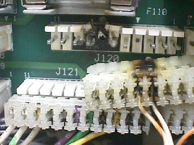
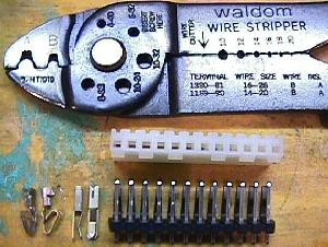
- Connector pins and housings: used to repair burnt connectors.
Alle componenten zijn verkrijgbaar bij Flipperwinkel.NL in Arnhem voor zeer scherpe prijzen.
1d. Getting Started: Different WPC Generations
- There
are essentially six different
generations of WPC systems. You
will need to know which
generation you have, because
components and some circuit
boards change with each
generation.
- WPC Alpha-Numeric: used from Funhouse (10/90) to The Machine BOP (4/91). This generation of WPC used 16 digit alpha-numeric displays. These also used "normal" flippers, without a Fliptronics board. Identified by no Fliptronics board in the upper left corner of the backbox, and no dot matrix control board in the upper right side of the backbox (some Dr.Dude games were also this WPC generation although most were System11). All Dr.Dude WPC and early Funhouse games used System11 sound boards.
- WPC Dot Matrix: used from Terminator2 (6/91) to Party Zone (10/91). This generation of WPC used "normal" flippers, without a Fliptronics board. Identified by no Fliptronics board in the upper left corner of the backbox. Most Party Zone games don't have Fliptronics boards, and fall into this category.
- WPC Fliptronics: Used from Addams Family (2/92) to Twilight Zone (5/93). Some late Party Zone games also used this generation of WPC. The Fliptronics (I) board used in Addams Family and Party Zone are slightly different than all later Fliptronics II boards. The difference being the addition of a bridge rectifier to the Fliptronics II board for the flipper voltage.
- WPC DCS: Starting with Indiana Jones (10/93), Williams upgraded the sound card to use "digitally compressed sound" (DCS) as a different sound compression system. This gave much better sound and more sound storage space.
A WPC-Security CPU board. The chip with
the white bar code label is the security PIC.
This chip is game specific. Replacements are
available only from Williams, for $180 each
(retail). Note the different battery placement
configuration on WPC-S CPU boards.
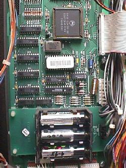
- WPC-Security (WPC-S): Starting with World Cup Soccer (3/94), a security PIC chip was added to the CPU board in all WPC-S games. This PIC (programable integrated circuit) chip was game specific. CPU boards can not be swapped between different models of game without changing the security PIC chip (i.e. Corvette CPU board put into a Shadow game must have the Corvette PIC changed to a Shadow PIC chip). Each security PIC chip had a special serial number encoded into the chip. This number displays on the dot matrix screen for a few seconds as the game turned on. The serial number showed what distributor the game was shipped to from the factory. This was done by Williams, because of problems in Europe, with distributors selling games out of their sales territory. Anyone could turn a game on, write down the displayed serial number, and determine if the game was "bootlegged" from another distributor. Unfortunately for us, the PIC chip makes CPU repair more difficult, as CPU boards can't be swapped between games without changing the PIC chip. To make things worse, new PIC chips are only available from Williams for about $180 (retail) each. They are priced at this amount to deter distributors who are bootlegging, from purchasing additional PIC chips. I personally wish that Williams would revise the U6 ROM code for all older games, disabling the need for a specific PIC chip (or price the PIC chips much cheaper). I see no disadvantage to this as older (used) games don't need distributor bootleg protection.
- WPC-95: Starting with Congo (3/96) (and some Jackbot games), Williams introduced a new WPC-95 CPU, driver board, and audio/visual system. The Fliptronics board is now incorporated into the driver board. The sound and dot matrix controller board are combined into one board. WPC-95 also used a security PIC chip. Most of the WPC-95 circuits are the same as WPC-S and earlier. Exceptions include putting all the dot matrix display and DCS sound driver logic into a single logic array chip (similar to the WPC chip on the CPU board).
1e. Getting Started: Game List
- Here
are the list of WPC games and
which generation they are.
- WPC
Alpha-Numeric
- Dr.Dude, 10/90 *
- Funhouse, 10/90 *
- Harley Davidson, 3/91
- The Machine BOP, 4/91
WPC Dot Matrix
- Terminator2, 7/91
- Gilligan's Island, 7/91
- Slugfest Baseball
- Party Zone, 10/91 *
WPC Fliptronics
- Party Zone, 10/91 *
- Addams Family, 2/92
- Hurricane, 2/92
- The Getaway, 4/92
- Black Rose, 8/92
- Fish Tales, 10/92
- Dr.Who, 12/92
- WhiteWater, 1/93
- Creature from Black Lagoon, 1/93
- Dracula, 5/93
- Twilight Zone, 5/93 #
WPC DCS
- Indiana Jones, 10/93 #
- Judge Dredd, 10/93 #
- Star Trek Next Generation, 11/93 #
- Demolition Man, 3/94 #
- Popeye, 3/94 #
- WPC-Security
- World Cup Soccer, 3/94
- Flintstones, 7/94
- Corvette, 8/94
- Red and Ted RoadShow, 11/94 #
- Dirty Harry, 3/95
- The Shadow, 3/95
- Theatre of Magic, 4/95
- No Fear, 5/95
- Indianapolis 500, 9/95
- Johnny Mnemonic, 10/95
- Jackbot, 10/95 *
WPC-95
- Jackbot, 10/95 *
- Congo, 3/96
- Who Dunnit, 3/96
- Attack from Mars, 3/96
- Scared Stiff, 3/96
- Safe Cracker, 5/96
- Tales of Arabian Nights, 7/96
- Junkyard, 1/97
- NBA Fast Break, 3/97
- Medieval Madness, 9/97
- Circus Voltaire, 11/97
- No Good Gofers, 1/98
- Championship Pub, 6/98
- Monster Bash, 9/98
- Cactus Canyon, 3/99
* These games share two different systems. Only about 100 Dr.Dudes are WPC (most are System11). Early production Funhouse and all WPC Dr.Dude games use System11 sound boards. Most Party Zone games are not WPC Fliptronics. Only a few Jackbot games were WPC-95.
Playfield Glass Size.
# - These games are "super-pins" with wide playfield bodies. These use 23 3/4" x 43" x 3/16" tempered playfield glass, instead of the normal 21" x 43" x 3/16" tempered playfield glass used on most other pinballs from the 1950's through WPC. Safe Cracker, a smaller pinball, uses 18.5" x 36.5" x 3/16" tempered playfield glass. - WPC
Alpha-Numeric
1f. Getting Started: Lubrication Notes
- Pinball
machines, for the most part, do
not require any lubrication.
Most parts run "dry".
You can do far more damage to a
pinball machine by over-lubricating,
than you can by under-lubricating.
As a rule, if you're in doubt as
to lubrication, don't do it!
Throw that WD-40 away, you won't
be using it here.
The only parts that will require any lubrication are metal-to-metal moving parts. There aren't very many in a game. Only ball eject and slingshot hinges. You may use 3-in-1 oil on these if you must. But try and keep that lubrication in your tool box and away from your game.
If some prior person did lubricate your game, the lubrication has probably now congealed with the infamous "black pinball dust" to form a thick, black mess. This is unrepairable on coil sleeves, and new parts will need to be installed.
1g. Getting Started: The Circuit Boards
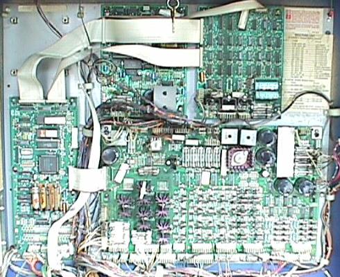
The back box in a 1991 Bally Gilligan's Island (second generation WPC). The CPU board is on the far left. The driver board is the largest board, and occupies the lower right area. The sound board is at the upper middle. The dot matrix controller board is at the upper right. The "missing" board (upper left) is where the Fliptronics board will be located on 1992 and later games. Note the four mounting posts for this missing Fliptronics board. Newer Fliptronics II boards use six mounting posts.
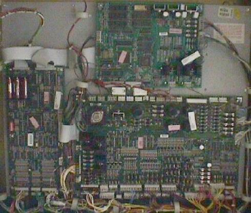
WPC-95 boards. Note fewer number of boards in WPC-95. The Fliptronics board is now incorporated into the Driver board. The dot matrix controller board and the sound board are combined into one board.- WPC
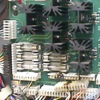
Power Driver Board.
Most of your repair work will probably relate to this board. The more familiar you are with the Driver board, the better you will be able to fix WPC games. The driver board drives all solenoids and lamps. It provides the power for almost all the parts of a WPC pinball game. It houses most of the fuses too.
A drawing showing the usage of the connectors, fuses and transistors on a WPC-S and prior Driver board.
1h. Getting Started: Introduction to Operation
- Much
technical information in this
section. If this makes you
uncomfortable, please skip. This
info is provided for completeness.
You don't need to understand it
to repair your WPC game.
Connector, Fuse and Board Numbers.
Every plug has a number that identifies the circuit board and position on the board that it connects to. For example, J101 designates board 1, jack 1. Identifying the pin number of a connector involves a hypen. For example, J103-5 means board 1, jack 3, pin 5.Fuses are also identified in this manner. For example, F501 means board 5, fuse 1.
Prefix number for WPC boards:
- 1 = Power driver board
- 2 = CPU board
- 3 = Display driver board
- 4 = Dual or single display board
- 5 = Sound board
- 6 = Dot matrix controller board
- 7 = Printer kit boards
- 9 = Fliptronics board
Circuit Board Descriptions.
- CPU board: The CPU board uses a 68B09 microprocessor and controls all logic and switch functions.
- Power Driver Board: Does not contain any game specific components. Contains the lamp, general illumination (GI), flipper (pre-fliptronics) and solenoic circuits. Also supplies +18 volts for the lamp circuits, +50 volts for the solenoids, +5 volts for the logic circuits, +12 volts for the switch circuits, and 6.3 volts for the general illumination circuits. Not game specific.
- Display Driver Board: part number A-12739. Used on pre-dot matrix WPC games. The hyphen after the part number indicates how many extended displays are used. No extended display is "-1", one extended display is "-2", and two extended displays is "-3".
- Single Display Board: part number A-12794. Used on pre-dot matrix WPC games, and contains one 16 digit alpha numeric display glass.
- Dual Display Board: part number A-12793. Used on pre-dot matrix WPC games, and contains two 16 digit alpha numeric display glass.
- Dot Matrix Controller Board: supplies the data for the dot matrix display to operate. Not game specific.
- Dot Matrix Display/Driver Board: contains the dot matrix glass and driver board. Not game specific.
- Sound Board: produces all speech and music.
CPU Board Operation.
CPU board perform two main operations: logic and switch control.- Microprocessor (U4): uses a 68B09E to control and process data. With an oscilloscope, the address and data lines should be square waves with at least 4 volts peak to peak. The processor runs at 2 mHz clock supplied by pins 81, 82 of the ASIC. Pins 34, 35 of the processor should be square waves, at least 5 volts peak to peak. Reset (pin 37), IRQ (pin 3), and R/W (pin 32) should also be at least 4 volts peak to peak during normal operation.
- ROM (U6): uses a 1 meg to 8 meg EPROM which contains the game program. Using an oscilloscope, the address and data lines should be 4 volts peak to peak square waves.
- RAM (U8): uses a 2064 CMOS RAM which store game specific audit information and adjustment settings. The battery circuit is connected to the cathodes of D1 and D2, which connect to U8 pins 26 and 28. When the game is on, pins 26/28 should have +5 volts peak. When the game is off, pins 26/28 should have at least +4 volts as supplied by the battery. If this drops below +4 volts, memory reset will occur.
- ASIC (U9): stands for Application Specific Integrated Circuit. This chip handles the address decoding, system timing, a real time clock, and system sequencing. Using an oscilloscope, the address and data lines should be at least 4 volts peak to peak. The other pins on this chip should have either a solid high or solid low with nothing floating. This chip is not game specific, but is specific to WPC. Provides two clocks (real time and system timing). The blanking circuit is monitored by the ASIC. Blanking is active during power on until the microprocessor is running, and has reset the latches to the normal operating modes. This prevents coils or motors from energizing when the game is turned on. Once the microprocessor has reset the latches blanking becomes +5 volts level.
- Miscellaneous Buffers/Latches (U1, U2, U3, U5, U7, U12, U21): used as temporary memory storage for the microprocessor. Address and data lines should be 4 volts peak to peak. Any address or data lines that are not pulsing should have a solid high or low, nothing floating.
Switch Matrix (all WPC games) Dedicated
Grounded
SwitchesColumn/
Row1
Green-
Brown2
Green-
Red3
Green-
Orange4
Green-
Yellow5
Green-
Black6
Green-
Blue7
Green-
Violet8
Green-
GrayD1 Orange-Brown
Left Coin Chute1 White-
Brown11 Right
Flipper21 Slam
Tilt31 41 51 61 71 81 D2 Orange-Red
Center Coin Chute2 White-
Red12 Left
Flipper22 Front
Door32 42 52 62 72 82 D3 Orange-Black
Right Coin Chute3 White-
Orange13 Start
Button23 Ticket
Dispenser33 43 53 63 73 83 D4 Orange-Yellow
4th Coin Chute4 White-
Yellow14 Tilt
Plumb24 Test
Position34 44 54 64 74 84 D5 Orange-Green
Service Credits5 White-
Green15 25 35 45 55 65 75 85 D6 Orange-Blue
Volume Down6 White-
Blue16 26 36 46 56 66 76 86 D7 Orange-Violet
Volume Up7 White-
Violet17 27 37 47 57 67 77 87 D8 Orange-Gray
Begin Test8 White-
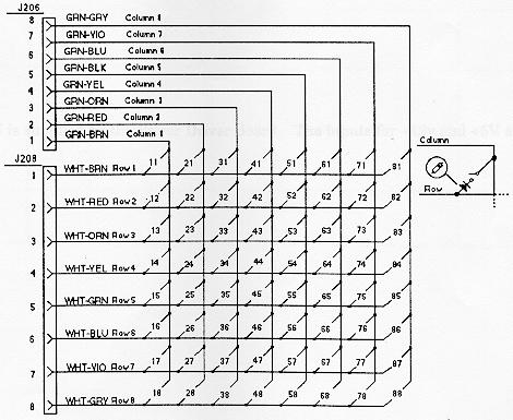
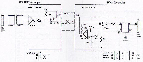
Gray18 28 38 48 58 68 78 88 - Switch Circuit: operates on +12 vdc. Most switches are tied to a column and row circuit. Some switches are "dedicated" and their curcuit is tied directly to ground through a switch. Playfield and cabinet switches make up the matrix, while the coin door makes up the dedicated switches.
Switch Matrix.
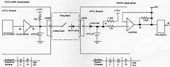
- Switch
Matrix Circuit:
microprocessor constantly
strobes the column side
of the switch matrix.
When the ULN2803 (column)
toggles low from a switch
closure, the column is
active.
When a switch closes, point C on the row circuit drops low, This causes the "+" input to the LM339 to go below +5 volts so point D is low, and the row is active. When corresponding row and column switch are low at the same time, the switch circuit is active and is registered as closed by the microprocessor. When the switch opens, point C on the row circuit is high, and the "+" input to the LM339 is at +5 volts. This makes point D high, and row is inactive.
- Dedicated Switch Circuit: these switches have the same circuit as the matrix row switches. The dedicated switch circuit operates the same as in the switch matrix circuit. When a dedicated swtich is closed, the circuit is driven low. Since the other side of the switch is tied to ground, the microprocessor recognizes the switch as being closed.
- Switch
Matrix Circuit:
microprocessor constantly
strobes the column side
of the switch matrix.
When the ULN2803 (column)
toggles low from a switch
closure, the column is
active.
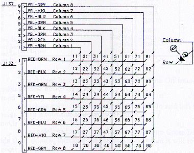
Dedicated Switch.

- Power Circuit: the power for the CPU is supplied by the Power Driver board. The inputs for +12 and +5 volts are on J210.
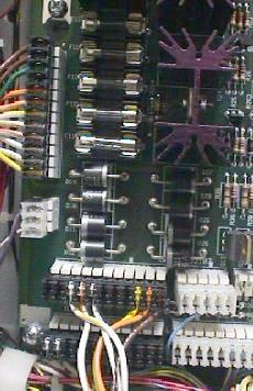
Power Driver Board.
The lamp, solenoid and general illumination (GI) circuits are driven from this board. The control for these circuits is provided by the CPU board.Lamp Matrix (all WPC games) Column/
Row1
Yellow-
Brown2
Yellow-
Red3
Yellow-
Orange4
Yellow-
Black5
Yellow-
Green6
Yellow-
Blue7
Yellow-
Violet8
Yellow-
Gray1 Red-
Brown11 21 31 41 51 61 71 81 2 Red-
Black12 22 32 42 52 62 72 82 3 Red-
Orange13 23 33 43 53 63 73 83 4 Red-
Yellow14 24 34 44 54 64 74 84 5 Red-
Green15 25 35 45 55 65 75 85 6 Red-
Blue16 26 36 46 56 66 76 86 7 Red-
Violet17 27 37 47 57 67 77 87 8 Red-
Gray18 28 38 48 58 68 78 88 - Lamp
circuit: To turn a lamp
on, the processor sends a
signal to the ULN2803
causing the output (point
A) to toggle low. This
causes the TIP107
transistor to conduct +18
volts, and it's output (point
B) to go high. At the
same time, the CPU board
(point G) drops the
output of a 74LS74 (point
F) to go high. This
causes the TIP102
transistor to conduct and
the collector of the TIP102
(point E) to go low. When
there is a high state on
the TIP107 (point B) and
a low stated on the TIP102
(point E), this completes
the circuit to a lamp and
the lamp lites.
The microprocessor shuts off the lamp circuit by changing point G to high. However, in overcurrent conditions the lamp circuit is shut off through the comparator (this is known as "strobing"). While the lamp is on, the .2 ohm resistor acts as a current sensor and the 1k ohm resistor and .22 mfd capacitor act together as a filter. These components monitor the row circuit and send a voltage signal to the input of the LM339 (point D). If the voltage at point D rises above 1.4 volts the output of the LM339 (point C) goes low, which is fed back to the 74LS74 and shuts the row circuit off. Once the row is shut off through the comparator, the processor must signal the 74LS74 to enable the row circuit again.
Lamp matrix.
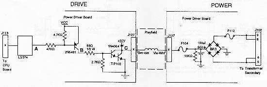
- Solenoid circuit: there are four types of solenoid circuits. High power, low power, flashlamp and general purpose. Most solenoids are pulsed (pulsed power output). Some solenoids are left on (relays and motors) for a specific time.
- High
power solenoids: operated
from +50 volts
unregulated power and
generally use a AE-26-1200
coil. This circuit
contains a TIP36 driver
transistor and a 1N4004
tieback diode to
dissipate the coil
induced voltages.
Solenoids 1 to 8 are high
power solenoids.
The microprocessor toggles the output of a 74LS374. When the 74LS374's output (point A) drops low, the collector of the pre-driver 2N5401 (point B) is high. This causes the collector of the TIP102 (point C) and the emitter of the TIP36 (point D) to drop low. This grounds the coil and the coil is turned on. The coil shuts off when the output of the 74LS374 (point A) goes high.
High Power Solenoid Circuit
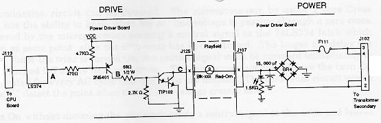
- Low
power solenoids: operated
from the same +50 vdc
unregulated power supply
as the high power
solenoids. This circuit
generally uses a AE-26-1500
coil and has a tieback
diode to dissipate the
coil enduced voltage.
Solenoids 9 to 16 are low
powered and use a TIP102
driver transistor.
The microprocessor toggles the output of a 74LS374 (point A) low, which makes the pre-driver 2N5401 collector (point B) go high. This causes the TIP102 collector (point C) and go low. This turns on the ground for the coil, which turns the coil on. The coil is shut off when the 74LS374 (point A) goes high.
- Low
power solenoids: operated
from the same +50 vdc
unregulated power supply
as the high power
solenoids. This circuit
generally uses a AE-26-1500
coil and has a tieback
diode to dissipate the
coil enduced voltage.
Solenoids 9 to 16 are low
powered and use a TIP102
driver transistor.
Low Power Solenoid Circuit
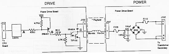
- Flashlamps:
operates on +20 volts
unregulated DC. This
circuit works the same as
the other solenoid
circuits, except it does
not use a tieback diode.
Drivers 17 to 20 are
flashlamps.
The microprocess toggles the output of a 74LS374 (point A) low. This turns on the pre-driver 2N5401 and the collector (point B) goes high. This causes the TIP102's collector (point C) to go low and complete the ground to the flashlamp. When the 74LS374 (point A) goes high, the circuit shuts off.
- Flashlamps:
operates on +20 volts
unregulated DC. This
circuit works the same as
the other solenoid
circuits, except it does
not use a tieback diode.
Drivers 17 to 20 are
flashlamps.
Flashlamp Circuit
- General
purpose: these are a
cross between the low
power coils and
flashlamps. The tieback
diode is optional and
determined by the wiring
harness. If the general
purpose solenoid is used
as a coil driver, the
diode is connected to +50
volts. If the general
purpose solenoid is used
as a flashlamp, the
circuit operates +20
unregulated volts DC and
the tieback diode is not
connected. Solenoids 21
to 28 are the general
purpose solenoids.
As with the other solenoid circuits, the microprocess toggles the output of a 74LS374 (point A) low. This turns on the pre-driver 2N5401 and the collector (point B) goes high. This causes the TIP102's collector (point C) to go low and complete the ground for the flashlamp or coil. When the 74LS374 (point A) goes high, the circuit shuts off.
- General
purpose: these are a
cross between the low
power coils and
flashlamps. The tieback
diode is optional and
determined by the wiring
harness. If the general
purpose solenoid is used
as a coil driver, the
diode is connected to +50
volts. If the general
purpose solenoid is used
as a flashlamp, the
circuit operates +20
unregulated volts DC and
the tieback diode is not
connected. Solenoids 21
to 28 are the general
purpose solenoids.
General Purpose Solenoid Circuit. Tieback diode (next to point C) not used when flashlamp is driven.
- General
Illumination (GI):
contains five separate
strings of up to 18 bulbs
per string, with a
maximum of 90 bulbs. Each
string is controlled by a
Triac, which is
controlled by the
microprocessor. The
microprocessor has
control of the triaces
through through a latch
that it uses to store
control signals. The GI
circuit can be dimmed.
The microprocessor has
the ability to know when
the AC line voltage is
passing through a zero
cross. Dimming is
achieved by the
microprocessor sending a
control signal to the 74LS374
latch, which turns the
triac on after the zero
cross has been detected.
The longer the delay, the
dimmer the bulbs.
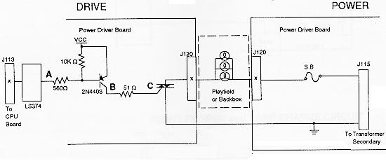
To turn the bulbs on without dimming the microprocessor sends a control signal to the triac, and leaves the signal applied. When the 74LS374's output (point A) goes low, the collector of the 2N4403 (point B) and the triac (point C) go high. This turns the triac on, which turns on its general illumination string.
- General
Illumination (GI):
contains five separate
strings of up to 18 bulbs
per string, with a
maximum of 90 bulbs. Each
string is controlled by a
Triac, which is
controlled by the
microprocessor. The
microprocessor has
control of the triaces
through through a latch
that it uses to store
control signals. The GI
circuit can be dimmed.
The microprocessor has
the ability to know when
the AC line voltage is
passing through a zero
cross. Dimming is
achieved by the
microprocessor sending a
control signal to the 74LS374
latch, which turns the
triac on after the zero
cross has been detected.
The longer the delay, the
dimmer the bulbs.
General Illumination (GI) circuit.
-
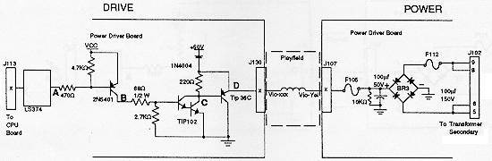
- Flipper Circuit: the microprocessor enables a relay to close. This enables a path to ground for the flippers. Flippers operated on +50 volts. An unloaded flipper has about 60 volts or greater. Loaded coils have about 48 volts.
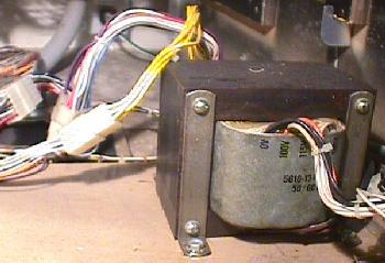
- Power Circuits: the power driver board supplies +5 vdc for the logic circuits, +12 vdc for the switch matrix and motors/relays, +18 vdc for the controlled lamps (lamp matrix), +20 vdc for the flashlamps, +50 vdc for the solenoids, and 6.3 vac for the GI. The +5 and +12 volts (switch matrix) takes the secondary AC voltage from the transformer and routes it to a bridge rectifier and capacitor. This converts the AC to unregulated DC. Then the unregulated DC goes through a voltage regulator which regulates the DC voltage. The +12 volt power, +18, +20 and +50 volt circuits are unregulated. The AC voltage from the transformer secondary goes to a bridge rectifier and capacitor, then to the necessary circuit. The 6.3 vac goes through the triacs and fuses, and then to the bulbs.
High Line/Low Line Voltage Detection Circuit.
WPC uses the +18 volts power circuit to monitor the AC line voltages for high or low line conditions. This circuit consists of a LM339 comparitor and two LEDs and a voltage divider. None of the controlled lamps can be on when checking the LEDs for proper voltage (have the game in test mode, not attract mode).- Voltage Ok: LED2=On, LED3=Off
- Voltage High: LED2=Off, LED3=Off (go up on transformer tap)
- Voltage Low: LED2=On, LED3=On (go down on transformer tap)
Dot Matrix Controller Board.
The dot matrix controller board provides the voltages for the display, and interfaces the display with WPC.The CPU writes a bit mapped image into RAM on the dot matrix controller board and can control which page area is displayed. The bit mapped image corresponds to the points on the dot matrix display. The RAM can store 16 full display images at one time. There are three 74LS175 page registers that give the CPU access to the RAM. The high and low page registers are accessed directly by the CPU. These page registers point to one of the 16 RAM areas each, for the CPU to read and write from. The third page register points to the RAM area which is actively displayed. There is one additional register that allows the CPU to know which row of the display the controller is currently updating. The dot matrix controller automatically mutiplexes and refreshes the screen according to the data in the RAM. The system clock controls access to RAM so there are no wait states.
The voltages necessary (except for +5 which is supplied by the power driver board) for the dot matrix display are provided by the dot matrix controller. The voltages are regulated DC +62 (power), +12 (logic), -125 (power), -113 (logic; -125 plus -113 gives +12 volts).
A 74HCL138 decoder at U1 selects whether to access the RAM (port) or Registers (control). Another 74HCT138 at U2 selects which registers to access.
The RAM circuit uses 74LS175's at U33 and U35 to control which page the system accesses. 74LS175's at U31 and u32 control which page is displayed. 74LS157 chips at U25, U26, U27 multiplex the access to the RAM between the controller board and the system according to the "E" clock. If the E clock is low, the system has access. If the E clock is high, the controller has access.
The control logic uses 74HCT161 chips at U10, U11, U12 to start the row scan. 74HC193 chips at U13, U14, U15 address the sequence of bits on the serial port to the display. U22, U21, U5 generate the interupt on a row being displayed which is determined by the system. U23, U6 function together as a row 1 detect circuit.
Dot Matrix Diplay/Driver Board.
The dot matrix display and attached driver board has a 128 column and 32 row gas discharge display unit. The column drivers have output latched so that the column data for the following row can be entered while the present is being displayed. The requires three positive and two negative voltages, a clock signal, and serial data similar to the type used to drive CRT displays.Sound Board.
The sound board produces all the music, sound and speech for a game. It has its own microprocessor (6809) running at 8 mHz to control and process data. IT also uses 2064 RAM for temporary storage.There is a DAC circuit which produces the standard game sounds (anything that is not speech or music). The DAC gets its information in digital format, converts it to analog, and send it to an amplifier.
There is also a speech circuit and a mixer cirucuit. The mixer circuit take the sound, DAC, and speech circuits and mixes them together. The mixed sound is sent to a MC3340 attenuator which controls the volume. Then the signal goes to the power amp which amplifies the sound before being sent to the speakers.
1i. Getting Started: Troubleshooting (quick guide)
This section is right from a 1991 Williams' "WPC theory of operation" manual (#16-9289). Since this manual is from 1991, DCS sound, fliptronics, and WPC-S and WPC-95 are not explicitely covered. But much of this information still applies to these newer WPC revisions.- CPU
board Troubleshooting.
The CPU has three LEDs located on the upper left side of the board (labeled D19, D20, D21). On game power on, D19 and D21 turn on for moment. Then D19 turns off and D20 starts to blink rapidly. D21 remains on. The system has detected a problem if:- D20 blinks one time: ROM error U6
- D20 blinks two times: RAM error U8
- D20 blinks three times: Custom chip U9 failure
CPU Problems and Potential Solutions.
- The
game stays in Factory
Settings or displays says
"Factory Settings
Restored".
This indicates that the CMOS RAM on the CPU board is no longer retaining it's custom settings, and has reverted back to the default settings. The three AA batteries are dead or not making good contact. Discussed further down in this repair document. - Game
displays "Time and
Date Not Set".
The real time clock is not running, or the three AA batteries are dead or not making good contact. - U6
Checksum Error.
Check chip U6 and socket for bent pins or cold solder joints. U6 is the main program EPROM for the game. - The
CPU is dead.
Very difficult to determin the cause. Biggest problem is that the address and data lines are almost always stuck low or floating. Check for +5 volts and proper ground. Check for a solder short or cold solder joints under any chip or socket. Check latches for activity. There should always be square waves about 4 volts peak to peak on the outputs. Check that the 8mHz and 32kHz clocks are running. If all else fails, swap U4, U6 and U9 one at a time to try to issolate the problem.
Switch Circuit problems and potential solutions.
- Game
comes up, but accepts no
coins and won't start a
game.
Check fuse F115 on the power driver board. Check switch #13, the start button, on the cabinet. The white-orange and green-brown wires must be connected to the switch blades. Check CPU connector J206, J207, J208, J209 for contamination. Check U20, pin 1; it should be high and pin 18 should be low. Check U18 pins 5, 2 which should be low. Check D5. - All
the switches in one
column are either dead or
active at the same time.
Check U20 and U14. Check that the swtich column wire is not shorted to ground. - All
the switches in one row
are either dead or active
at the same time.
Check the corresponding 1N4148 diode and LM339 comparator. Check U13 and U15. - The
game won't go into
diagnostics.
Check the diagnostics switch on the coin door. Be sure the ground wire is connected. Check U15 and J16. Check connector J205 for contination. - Two
or more unrelated
switches act together.
Check for a defective diode on the switches and that none are touching metal. Check for solder shorts on the CPU in the switch circuit. - The
game comes up with "Check
Switch #" in the
display.
Indicates that the switch shown has not been activated in about 30 games. Check the LM339 that controls that switch, and check U20. Be sure the wires or the diode have not broken off. The game compensates for an inactive switch to allow nearly normal game play. - The
Games says "Pinball
Missing".
A pinball is missing or stuck on the playfield. Another cause could be the outhole switch is not working. Check the wires and diode on that switch. Check U20 and the LM339 that controls the outhole switch. - The
game says "## Switch
is stuck On".
This indicates that a switch which is normally off is stuck on. This switch is essential for game play (coin chute or tilt). Be sure the swtich has the column and row wires attached, and not shorted. - Game
says "Wht-xxx Row x
Short".
This indicates a switch row is shorted to ground. Check that the coin door switch is not touching the ground coin door. Check that a leaf switch on the playfield is not touching a grounded playfield part. - The
game won't go into Game
Over mode.
Check the outhole switch. Be sure the wires are not broken. Check U20 and the LM339 and swtich diode. - Flipper
switches (11 and 12) do
not register.
This can be caused by either U7 or U8 on the power driver board, or by U20 or U18 on the CPU board. - Lane
change swtich doesn't
work.
This is almost always U7 (left flipper) or U8 (right flipper).
Lamp Circuit problems and potential solutions.
- None
of the lamp matrix (controlled)
lamps work.
Check LED6 on the power driver board. If it is off, check F114 and BR1. If it is on, check U9 and U18. Both chips should have high pulses on the outputs. Be sure the +18 volt wire is not broken. In rare cases, the transformer winding for the +18 volts can fail. - A
lamp row is either very
bright or dead.
The TIP102 for that row is mostly likely dead or locked on. The LM339 comparator is the next component to check. Occasionally the 74LS74 can cause a problem. Hint: a fast way to tell if the TIP102 transistor is defective is to ground the tab of the transistor. If you ground the tab and nothing happens, the transistor is probably good. If you ground the tab and the row lights, the transistor is probably bad. - A
lamp column stays on all
the time.
Most likely the column's TIP107 transistor is bad. - A
lamp row stays on all the
time.
Most likely the row's TIP102 transistor is bad. - A
few unrelated bulbs never
turn on.
Check the bulbs and the sockets. Be sure the column and row wires are soldered to the socket. If bulb is mounted in a PC board, check the male pin connectors on the board for bad or cold solder joints. - All
the lamps stay on and
never turn off.
Most like U9 is defective. Note U18 could have failed at the same time.
Coil problems and potential solutions.
- None
of the +50 volt solenoids
turns on.
Check fuse F112 and bridge BR3. - I
have a motor or relay
that doesn' work.
Check fuse F103, the TIP102 transistor that drives the motor or relay, and the wires going to the device. The device itself can also be defective. - I
have a coil that won't
kick.
Check the TIP36 and/or the TIP102 transistor that drives the coil. Check the 2N4403 pre-driver transistor. Be sure a wire hasn't broken from the coil. Check the +50 volts from the power side of the coil to ground. It is possible, but unlikely, that the 74LS374 latch could fail. Hint: a fast way to tell if a TIP102 transistor is defective is to ground the tab of the transistor. If you ground the tab and nothing happens, the transistor is probably good. If you ground the tab and the coil kicks, the transistor is may be defective (assuming the coil doesn't work in game or test mode). - I
have a coil that stays
energized.
The TIP36 and/or TIP102 transistors may have failed and locked on. Check the 2N4403 driver transistor too. For this problem, grounding the tab of the transistor will not help determine the problem. - A
coil has burned.
If there is a burnt coil on the playfield, there is probably damage to the power driver board too. If you replace the coil before checking the power driver board, you could damage the new coil.
The coil itself could be defective too. Or the 74LS374 latch or driver transistor(s) could have shorted and caused the coil to stay energized. Another problem could be the BR3 bridge. However, if BR3 fails fuse F112 usually also blows (and there's more than one coil effected).
Be sure that the coil is not touching a grounded metal part under the playfield. Or that there is not a mechanical problem holding the coil in the energized position. - Two
or more coils activate at
the same time.
Check for clip shorts on the power driver board. Check the 74LS374 latch that controls the coils. Check for a short under the playfield between the drive wires of the coil. - Fuse
F111 or F112 blows.
The BR3 or BR4 bridge(s) are defective. Another cause is a shorted flashlamp socket or a shorted coil. A defective relay or motor will also cause this. Note: if F111 or F112 blows more than once there is probably damage on the power driver board.
Flashlamp problems and potential solutions.
- I
have a flashlamp that
never lights.
Check the bulb. Check the TIP102 transistor that drives the flashlamp. Be sure the wires that go to the flashlamp socket are not broken. The 2N4403 pre-driver transistor can also cause this problem. - I
have a flashlamp that is
always On, and/or that is
very bright.
Check the TIP102 and 2N4403 transistors that drive the flashlamp. The 74LS374 latch sometimes causes a flashlamp to stay on. - None
of the flashlamps turn on.
Check for +20 volts at the bulb socket. Check fuse F111 and bridge BR4. F111 is probably blown. - One
or two flashlamps seem to
burn out more often than
the rest.
There is probably more than +20 volts getting into the flashlamp circuit. Check the voltage from the flashlamp to ground. If there is more than +20 volts, on of the wires going to that bulb is coming in contact with anouther voltage section. If the voltage is correct, then the TIP102 transistor is probably bad.
General Illumination problems and potential solutions.
- A
single GI string of bulbs
doesn't turn on.
Check the fuse that controls that string. If the fuse is good, check to see if there is voltage at the bulb sockets. If there is no voltage, the wire going from the fuse to the bulbs is open. If there is voltage, check the triac that drives the GI string. - None
of the GI bulbs turn on.
Check the 74LS374 latch. Check for 6.3 volts AC coming to the power driver board from the transformer. - A
single GI string doesn't
dim.
Most likely the triac that controls that string is defective. The 74LS374 latch might cause this problem. - None
of the GI strings dim.
Most likely the 74LS374 latch or the zero cross circuit is defective. If the zero cross circuit is defective, it probably the LM339 comparitor. In rare cases the microprocessor would cause such this problem. - The
GI strings don't turn off.
The zero cross circuit is the problem. Most likely the LM339 comparitor is defective. In rare cases the microprocessor would cause such this problem.
Power circuit problems and potential solutions.
If any of the power circuits on the power driver board fail, check the corresponding fuse first. If this isn't the problem, or a new fuse blows immediatly, check the circuit's bridge rectifier and voltage regulator. Other possibilities:- Shorted G.I. socket can cause F106-F110 to blow.
- Shorted flashlamp socket can cause F111 to blow.
- Shorted coil can cause F101-F105 and F112 to blow.
- A +5 vdc short to ground can cause F113 to blow.
- Shorted controlled lamp socket can cause F114 to blow.
- Defective U20 can cause F115 to blow.
Alphanumeric display problems and potential solutions.
Since the display driver and the dual or single display boards are separate boards, the first thing to do when troubleshooting is to swap the boards to isolate the problem.- Segments
are missing.
Usually caused by a defective UDN-7180. The 74LS374 could also fail along with the UDN-7180. - Digits
are missing.
Usually caused by a defective UDN-6118. The 74LS240 could also fail along with the UDN-6118. - No
displays.
Check fuse F301. Be sure you have +/- 90 volts. - Digits
strobe slowly across the
display.
The +/- 90 volts had dropped down to about +/- 30 volts. Check the power supply circuit on the display driver board. - Segments
bleed into one another.
One of the ribbon cables from the display driver board to the single or dual display boards is on backwards.
Dot matrix display problems and potential solutions.
- Dots
are missing from the
display.
Check the display glass for a disconnected or broken or mis-soldered pin. - Columns
are missing from the
display (in blocks of 32).
On or more of the column drive chips are defective. - No
display at all.
Display/driver board is defective, or the correct voltage is not being supplied by the controller board. - The
display is unreadable.
The RAM on the controller board is defective. - The
display repeats the wrong
pattern.
One or more of the latches going to the RAM on the controller board are defective.
Sound problems and potential solutions.
- No
sound.
Usually the AD7524 DAC is defective. - No
speech.
Usually the 55536 CVSD, or the TL040 op-amp, or the TL082 op-amp are defective. - The
speech is distorted.
Usually a defective 55536 CVSD, or a defective 74LS74. - No
music.
Usually the YM3012 or the YM2151 are defective. - The
volume level is too low
and the volume control is
not the problem.
Check the TL084 and the TL082 op-amps. - No
output at all.
The LM1875 audio amp is probably defective. This amp should have -26 volts on pin 3, and +26 volts on pin 5. Anything else indicates a problem. The sound ROM or RAM could be defective. There should be high pulses on the output pins of the Sound ROM and RAM. The MC3340 attenuator can also cause this problem. - The
board is dead.
There is probably no +12 or -12 volts. Check fuse F501 and F502. - Sound
Board Error codes at game
power-on:
- 1 beep = sound board Ok
- 2 beeps = U9 RAM failure
- 3 beeps = U18 ROM failure
- 4 beeps = U15 ROM failure
- 5 beeps = U14 ROM failure
- Wat voor
kennis op dit gebied wordt er van je
verwacht ?