- On the under the playfield eddy sensor control board, turn the potentiometer counter-clockwise until the LED just turns on.
- Now turn the potentiometer back clockwise until the LED just turns off.
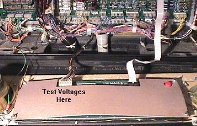
- Pin 1: -125 volts
- Pin 2: -113 volts
- Pin 3: Key
- Pin 4: Ground
- Pin 5: Ground
- Pin 6: +5 volts
- Pin 7: +12 volts
- Pin 8: +62 volts
- MJE15030: Q1 on WPC-95, Q3 on WPC-S and prior. Controls the +62 volts. Connects to F601 to BR1 (and D3 and Q2, Q10 and R4, R3, R12 on WPC-S and prior).
- MJE15030: Q7 on all WPC versions. Controls the -113 volts (connects to Q6 and D6 and R8, R9 on WPC-S and prior).
- MJE15031: Q6 on all WPC versions. Controls the -125 volts (and -113 volts). Connects to F602 to BR2 (and D4, D5 and Q4, Q5 and R5, R6, R13 on WPC-S and prior).
- MPSD02: Q2, Q10 on WPC-S and prior. Q2, Q3 on WPC-95.
- MPSD52: Q4, Q5 on WPC-S and prior. Q4, Q5 on WPC-95.
- 2N3904: Q1 on WPC-S and prior only).
- 1N4759 (62 volts): D3 on WPC-S and prior. D2 on WPC-95.
- 1N4758 (56 volts): D4, D5 on WPC-S and prior. D1, D18 on WPC-95. Doesn't fail as often as the other above listed components.
- 4.7k ohms, 5 watts: R8 on WPC-S and prior, R43 on WPC-95. Replace if it looks at all damaged, even if it measures OK.
- 1.8k ohms, 5 watts: R9 on WPC-S and prior, R44 on WPC-95. Replace if it looks at all damaged, even if it measures OK.
- 120 ohm 1/2 watt resistors at R4, R5 (WPC-S and prior only).
- 47k ohms 1/2 watt at R3, R6, R12, R13 (WPC-S and prior only).
- At power-on, D19 and D21 should be ON. D20 should be OFF.
- During normal operation, D19 should be OFF. D20 should be FLASHING.
D21 should be ON.
Problem Power-On CPU D20 (diagnostic) Flash Codes:
- blinks ONE time: U6 CPU game ROM bad
- blinks TWO times: U8 CMOS RAM chip bad
- blinks THREE times: U9 WPC custom chip bad
- 1 Beep: Sound board OK
- 2 Beeps: U9 sound ROM failure
- 3 Beeps: U18 sound ROM failure
- 4 Beeps: U15 sound ROM failure
- 5 Beeps: U14 sound ROM failure
- 1 Beep: Sound board OK
- 2 Beeps: U2 sound ROM failure
- 3 Beeps: U3 sound ROM failure
- 4 Beeps: U4 sound ROM failure
- 5 Beeps: U5 sound ROM failure
- 6 Beeps: U6 sound ROM failure
- 7 Beeps: U7 sound ROM failure
- 8 Beeps: U8 sound ROM failure
- 9 Beeps: U9 sound ROM failure
- LED1: +12 volts DC switch matrix circuit, normally ON.
- LED2: high/low line voltage sensor, normally ON.
- LED3: high/low line voltage sensor, normally OFF.
- LED4: +5 volts DC digital circuit, normally ON.
- LED5: +20 volts DC flashlamp circuit, normally ON.
- LED6: +18 volts DC lamp matrix circuit, normally ON.
- LED7: +12 volts DC power circuit (motors, relays, etc), normally ON.
- At power-on, LED201 and LED202 should be ON. LED203 should be OFF.
- During normal operation, LED201 should be OFF. LED202 should be ON.
LED203 should be FLASHING.
Problem Power-On CPU LED203 (diagnostic) Flash Codes:
- blinks ONE time: G11 CPU game ROM bad
- blinks TWO times: U8 CMOS RAM chip bad
- blinks THREE times: G10 Security PIC chip bad or for different game
- LED501: +5 volts DC, normally FLASHING (but at a slower rate than CPU LED203).
Problem Power-On Audio/Visual Board Beep Error Codes:
- 1 Beep: Audio/Visual board OK
- 2 Beeps: S2 sound ROM failure
- 3 Beeps: S3 sound ROM failure
- 4 Beeps: S4 sound ROM failure
- 5 Beeps: S5 sound ROM failure
- 6 Beeps: S6 sound ROM failure
- 7 Beeps: S7 sound ROM failure
- 10 Beeps: Audio/Visual board's Static RAM bad
- LED100: +12 volts DC regulated, normally ON.
- LED101: +5 volts DC digital, normally ON.
- LED102: +18 volts DC lamps, normally OFF.
- LED103: +12 volts DC un-regulated, normally ON.
- LED104: +20 volts DC flashlamps, normally ON.
- LED105: +50 volts DC coils, normally ON.
- Remove the backglass and gain access to the CPU board.
- Turn the game ON.
- Note the orientation of the installed batteries (All positive terminals up or to the right?).
- Remove the old batteries and discard.
- Check the battery holder's terminals for any corrosion. Clean with 220 grit sandpaper if any corrosion. If damaged, turn game off and replace battery holder.
- Using a Sharpie pen, write today's date on the new batteries.
- Install the new batteries.
- Turn the game off.
- Excellent grounding
- MOV (metal oxide varistor)
- Line fuse
- Power transformer (all voltage goes through a transformer)
- Bridge Rectifiers
- North America (115 volt power): 150 volt or 130 volt MOV.
- Europe (220/240 volt power): 275 volt MOV.
- Re-seat all the sound board ribbon cables. Surprisingly, this fixes a large number of WPC sound problems!
- Bad rectifier diodes on the sound board. Often these become leaky and can cause intermittent problems before they total short.
- Speakers blown: yes this happens more often than you might think. If the game was in a noisey arcade, the volume could be up so loud it blows the speakers. You can test the speakers (with the game off) using a 9 volt battery. Momentarily hook the battery up to the leads of the speaker. You will hear the speaker cone pull in if the speaker is good, when you attach the battery to the speaker. Make sure you check the speaker in the bottom of the cabinet too. Often if one speaker is blown, the others will not work.
- Main amplifier is bad: the sound board uses a LM1875 as the main amplifier. This device has a large heat sink attached to it. Often, this component has heat failure. The sound works fine until the game warms up for five minutes or so. Then the sound starts cutting in and out. You can use a logic probe on the leads of the LM1875. If the probe's beeps correspond to the cut in sound on one of the leads, the LM1875 is probably bad.
- If the LM1875 isn't at fault, check both of the op-amps too. Depending on the revision of the sound board (DCS or pre-DCS), these audio amps can effect a certain type of sound they amplify.
- On DCS games, the DAC for the DSP chip dies, and the TDA2030 amps are pretty fragile too.
- At power-on, D19 and D21 should be ON. D20 should be OFF.
- After the CPU board "boots" (during normal operation),
D19 should be OFF. D20 should be FLASHING. D21 should be ON.
Problem Power-On CPU D20 (diagnostic) Flash Codes:
If D20 blinks at power-on, and then stops blinking, here is what the blinks translate to:- blinks ONE time: U6 CPU game ROM bad
- blinks TWO times: U8 CMOS RAM chip bad
- blinks THREE times: U9 WPC custom chip bad
- At power-on, LED201 and LED202 should be ON. LED203 should be OFF.
- During normal operation, LED201 should be OFF. LED202 should be ON.
LED203 should be FLASHING.
Problem Power-On CPU LED203 (diagnostic) Flash Codes:
If LED203 blinks at power-on, and then stops blinking, here is what the blinks translate to:- blinks ONE time: G11 CPU game ROM bad
- blinks TWO times: U8 CMOS RAM chip bad
- blinks THREE times: G10 Security PIC chip bad or for different game
- Pins 1,2,3 = ground
- Pins 4,5 = +5 volts DC
- Pins 6,7 = +12 volts DC
3h. When things don't work: Infrared Optic Switches
-
As early as 1982, Williams started using infrared optic light emitting diodes (LED's)
for switches. This is similar technology to what is used in TV remote controls
today. These optics have two advantages over conventional mechanical switches:
no moving parts, and they can fit in tighter spaces. They also have some
disadvantages. They consist of two parts (instead of one part like a
micro-switch): a transmitter (the LED that emits the light), and the
receiver (the LED that receives and interprets the light). They can also
get dirty (from that infamous black pinball dust), and not work.
They are always on. That is, the light emitting half of an
opto switch is always powered on, as long as the game is
powered on. LED's aren't much different than light bulbs; they
eventually burn out too.
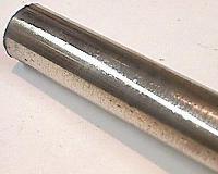
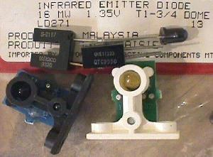
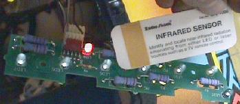
Several different optos used in Williams games. The "U" shaped
optos are used for Fliptronics flippers, Twilight Zone clocks, etc.
These consist of a transmitter and receiver in one package. The stand-up
optos are two parts: the green board opto stand-up is the transmitter,
and the blue board opto stand-up is the receiver. The transmitter
LED is larger and protrudes further from its case. The single diode
shown is a replacement LED transmitter for the stand-up optos, and
for opto boards used in ball troughs, etc.
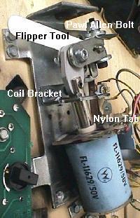
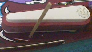
Optos are used on fliptronics
flipper switches. Note the plastic
activator arm that moves between
the "U" shaped optos. Originally
Williams made these from metal,
but switched to plastic to save
money. The plastic version can
often warp so they don't clear
the opto, causing a flipper not
to work.
-
Where Optos are Used.
Williams uses optos for lots of applications. WPC Fliptronics flipper buttons are opto activated. Many clear ramps have opto ball sensors. Many pre-1990 Williams drop targets use optos (they stopped using them there because the leads would break from vibration, and the optos would fall off). All WPC-DCS (1993) and later games use optos to sense balls in the ball trough.
Two parts to a opto switch.
Each opto switch has two parts; a transmitter and a receiver.
The transmitter is a infra-red LED (light emitting diode).
The receiver is a light sensitive transistor. The transmitter
is always on when a game is powered on. If the light beam
from the transmitter is interrupted, then this registers the
switch as "open".
Because the transmitter is always on and producing light (and hence heat), the transmitter is the part that fails 98% of the time in a opto switch.
-
Cleaning Optos.
Optos can get dusty from the "black dust" inside a game. To clean an opto, use a Q-tip dipped in glass cleaner. Wipe the opto with the Windex-wet Q-tip, then dry the opto with a clean, dry Q-tip. Do NOT use canned air to blow optos clean! The air in these cans is too cold and can damage an opto.
Testing Opto Switches.
Testing infrared optos switches is no different than testing
mechanical switches (to a point). Just use the WPC internal test software.
Press the "Begin Test" button inside the coin door, and go to the Test menu.
Select the "switch edge" test. Activate an opto switch by passing something
in front of it. The display will indicate if the switch works.
If an opto switch doesn't work, first check that your +12 volts is working. If you have blown the +12 volt fuse, there will be no power to the optos, and they won't work.
If there is +12 volts going to the opto, there is a good chance the transmitter has failed. To test the receiver, first put the game into the "switch edge" test. Then block the opto transmitter with a piece of tape. Now shine a penlight flash light into the receiver. The switch should "close". When you remove the light, the switch should "open". If the receiver is working properely, there's a good chance the transmitter has burned out.
If you have +12 volts in your game (Hint: do other optos work?), and the opto switch doesn't register in the diagnostic test, your opto transmitter is probably burnt. The receiver side of an opto switch almost never dies. That's because it only senses light, and doesn't produce light. The transmitter will be the offending unit 98% of the time. But there is a good way to test the transmitter side of an opto switch.
assembly. The LED's can be seen lit in this photo, but you won't
be so lucky with the naked eye. That's why this Infrared Sensor
card is so handy.
-
Radio Shack sells a $5 credit card sized "infrared sensor".
If you put this card right in front of an opto transmitter, you
can see if the opto is emitting light. The light will show on the colored
band of the sensor card only.
Optos on Newer WPC games.
Older WPC games use optos with straight resistive photocells.
Newer WPC games use a transistor gate photocell. This means the internal
transistor can die, even if the photocell part of the opto is OK. Keep
this in mind; if an opto transmitter tests good (with your Radio Shack
test card), the opto could still not function properely. Replacing the
opto is the only thing that will fix it.
The Opto Receiver and Transmitter Tests Good, now what?
If the receiver tests good with the penlight flashlight, and
the transmitter tests good with the infrared sensor card, there
is one more thing that could be wrong. This would be the LM339
voltage comparitor on the opto board. If everything else checks
out, replace ALL the LM339 chips (and use sockets!) on the
opto board (there are usually two of these chips on the opto board).
WPC Fliptronics Flipper Optos.
If a WPC Fliptronics flipper doesn't work, and it's not a coil, transistor or
wiring related problem, you should suspect the flipper opto board. This board
has two "U" shaped optos that detects the flipper button. These boards are all made
with two optos, even if the game only has two flippers instead of four.
Use your infrared sensor card to determine if the opto is working on the flipper board. If you suspect a problem with this opto (and don't have a infrared sensor card), you can swap the left and right flipper opto boards, and see if the problem moves to the opposite flipper. Note: you must have both flipper opto boards plugged in for this test to work! Opto board power is jumped through the left opto board. Both opto boards must be plugged in for the right one to work!
If indeed one of the flipper optos is bad, and your game only has two flippers, you can reverse the two optos on the bad flipper opto board. One of the optos will be unused since the game only has two flippers, instead of four. Mark the bad opto, and its position on the opto board. Then unsolder both optos, and throw the bad one away. Then re-solder the good opto into the marked position on the flipper opto board.
Weak Flippers and Bad LM339's on the Fliptronics Board.
On WPC fliptronics to WPC-S board, chips U4 and U6 (LM339) on fliptronics
board can fail. On WPC-95, these LM339 chips are on the CPU board
at locations U25 and/or U26. This will make
the flipper opto boards seem like they are not work. Swap the two
flipper boards to test this. If the problem doesn't change, suspect
the LM339 chip(s). These LM339 chips can
also become "leaky". This will make flippers seem very weak.
A bad LM339 can also give the indication that the EOS switch is bad.
If there is a marginal flipper switch reading, this causes the high powered side of the flipper to rapidly oscillate between on and off. The holding side of the flipper coil never engages. This problem will cause the flipper coil to get very hot in a short time.
Replacement Optos.
Unfortunately, optos are fairly expensive (compared to micro-switches).
For example, if you are repairing your Twilight Zone clock (which means
replacing all eight of the "U" shaped optos), this can get expensive.
The cheapest I've found these optos is from Competitive Products Corp (800-562-7283)
for $5 each (long leads too!). For non "U" shaped opto applications, you
can get infrared opto LED transmitters cheaply (get a transmitter voltage of
1.0 to 1.4 volts). Note the color of the opto doesn't matter, just as long as it's an
infrared emitting LED. Radio Shack sells the infrared LED, part number 276-143C
(replaces Williams A-14231). Radio Shack also sells an infrared transistor (receiver),
part number 276-145A (replaces Williams A-14232).
The industry part number for the "U" shaped optos is QVE11233, with a standard sensitivity of .0110. Unfortunately, Williams requires a higher sensitivity opto for their applications. This means the cheap $1 optos from most electronic supply houses won't work, as their sensitivity rating isn't high enough. If you are shopping for these "U" optos, keep this in mind. You should be looking for part number QVE11233.0086, where .0086 is the increased sensitivity rating.
3i. When things don't work: Eddy Sensors (electronic ball sensors)
-
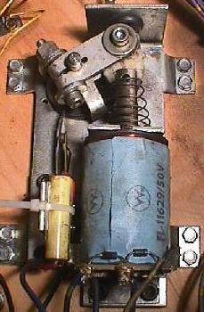
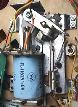
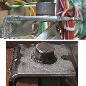
Starting in 1993, Williams starting using "eddy sensors" to determine
when a pinball rolled under a portion of the playfield. A eddy sensor
is a electronic switch; it has NO moving parts. It can sense when a
steel pinball passes over it, and acts like regular mechanical switch. Star
Trek Next Generation and Theatre of Magic uses these eddy sensors.
These electronic switches are used in playfield areas where a regular
mechanical switch is not practical or visually pleasing.
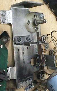
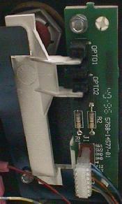
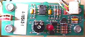
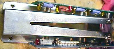
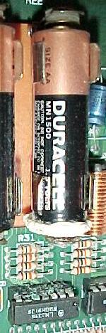
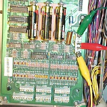
used on Theatre of Magic. Note the potentiometer and
LED. The connector on the left goes to the actual
under-the-playfiled mounted "sensor" (see pictures
below) that tell this board there is a ball above it.
-
Often eddy sensors can go out of adjustment and become less
sensitive. This can cause the eddy sensor to not activate
when a ball passes above it on the playfield. To adjust an
eddy sensor do this:
That is all that is required to adjust an eddy sensor. To test the sensor, put the game into WPC diagnostic's first switch test. Then move a pinball over the playfield area where the eddy sensor is located. The switch should activate on display.
Twilight Zone Eddy's.
Note eddy sensors were used as early as Twlight Zone. The eddy
sensor in TZ are different than the later sensors, and does NOT have
an adjustment pot (they also are called a different name, like
the "Trough Proximity" board). The eddy sensor that causes the most trouble in
Twilight Zone is the sensor by the ball trough (switch# 26). Usually
the problem is the molex connector. Just taking the two pin molex connector
off and putting it back on its header pins will usually the problem. If not,
this small board often needs to have its molex header pins resoldered.
Also, it is possible for the TDA0161 (Williams part number 5370-13452-00)
chip to die on this board. If you don't want to replace just this chip, the whole
proximity board is available for under $15.
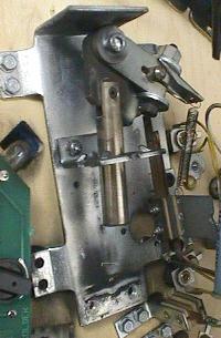
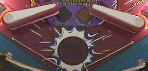
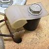
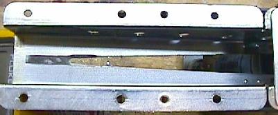
used on the outlanes of many games.
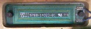
Right: another type of eddy sensor that senses the ball. This sensor is
used in Theatre of Magic and covers a wider area.
3j. When things don't work: Ball Trough Problems (random multi-ball)
-
The ball trough is the area where the balls drain and collect when
a game is over.
Up to 1993, Williams used a conventional ball trough design. This old
style ball trough used mechanical switches to sense the ball's
presence. It also used two coils to move the balls; one to kick the ball from the
outhole to the trough, and another coil to kick the ball from
the trough to the shooter lane.
Starting in 1993 with Indiana Jones, a new ball trough design was used that instead relied on gravity to feed the ball into the trough. This saved one coil (the outhole coil was no longer needed). The new design also used opto switches instead of mechanical switches. This allowed one ball trough design to be used in all Williams games, regardless of the number of balls used in the game. The ball trough could now comfortably hold from one to seven balls (depending on the game).
the balls. Note the large blue resistors used on the top board. Often
these resistors can vibrate and break. This will give the opto board
false ball senses or no ball senses.
-
Ball Trough problems: Random Multi-Ball.
When the opto ball trough was first used on Indiana Jones, William bolted the opto boards right to the side of the trough. The vibrations from the trough often caused the leads on the large blue resistors and the infra-red LED's on the opto transmitter board to break. This would cause the game to start random multi-ball at just about anytime during the game. Often the game would never end (because the trough would not reconize when all the balls had drained).
To fix this problem, Williams redesigned the attachment points for the two opto boards. Instead of being bolted directly to the trough, the mounting holes on the opto boards were enlarged (and one hole moved). Then special rubber gromets where inserted into the holes. Lastly, 1/4" metal tubes where inserted through the rubber gromets. When the opto board bolts where tightened down, they tightened on the metal tubes. This allowed the opto boards to "float" on the rubber gromet, reducing vibration considerably.
Ball Trough Upgrade Kit.
If you want to upgrade your Indiana Jones ball trough
to the current design (and solve your random multi-ball
problems), you can order an upgrade kit, part# A-18244.
This includes two new opto boards, and all the mounting
hardware needed (the mounting hardware is absolutely
necessary). At $50, this is an expensive kit! With
some thought and a good hardware store, you can modify your
original opto boards to mount like the newer style. It will
require enlarging the mounting holes on your existing opto
boards. You will also need to find some rubber gromets and small metal tubing
(hobby shops often carry this).
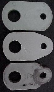
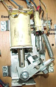
And if you use the newer metal trough #A-16809-2 (as currently
sold by Williams), you will also
need to move one of the large blue
resistors to the back of the board, and drill a new mounting hole in the
opto board. If you want to just be done with it (and spending $50 is not an issue),
just order the upgrade kit from Williams, part# A-18244, and get the two
new trough opto boards and the mounting hardware.
being worn in the ball trough. These cause the balls to hang and not roll
the length of the ball trough.
-
Ball Trough Divots.
Another problem with the new ball trough design is "divots". As the pinballs fall into the ball trough from the playfield, they eventually dig divots into the metal. This can cause the balls to hang and not roll the length of the ball trough and down to the shooter lane upkicker coil. All sorts of weird game problems can occur from this. The most common is trying to start a game by pressing the start button, and the game responds with "pinballs missing", or a game that doesn't end when the ball drains.
To fix this, you can often use a Dremel tool and grind the divots out of the metal. If this doesn't work, you can order a new ball trough, part number A-16809-2. This newer design of the ball trough should last longer and divot less.
More Random Multiball: the Ball Trough Optic Resistors.
The ball trough optic boards have several large blue resistors mounted to them.
Since these board get a fair amount of shock and vibration from balls,
often these resistors can break. If this happens, you'll can get random
(and continual) multiball. Check these large blue power resistors for
breaks or cracks. Usually the resistor leads break right where they
connect to the circuit board.
3k. When things don't work: Dot Matrix/AlphaNumeric Score Displays
-
Dot matrix displays are one of the coolest features on a WPC game. They
provide the score and graphic animations, and even video games within
the pinball game. Note that the first three WPC games (Funhouse, Harley Davidson, the Machine)
used the older style AlphaNumeric displays.
WPC Alpha Numeric Score Display Problems.
The first three WPC games that used AlphaNumeric displays have a common
problem. The resistors R48 and R49 (39k ohm) on the AlphaNumeric Display board
often fail and go open, or go out of spec. This can cause all the score displays
in the game to work very weak, or not work at all. Before replacing a score
display, replace BOTH of these 39k resistors with "flame proof" 1 or 2 watt
versions. See the Williams System 11 repair guide at
http://marvin3m.com/sys11/index3.htm
for more information
on repairing AlphaNumeric score displays. All the information there applies
to these three WPC games (though the component label numbers will be
different).
some characters in the display (on the right side).

-
Dot Matrix Displays.
The unfortunate part about dot matrix displays (DMD) is they wear out. Time will eventually kill these, and the display will "outgas" and fail. Because of the high voltage involved with score displays, the anode and/or cathode inside the diplay glass breaks down. This results in the "outgassing" of impurities that eventually change the internal gas properties, so the display can't glow (the gas must be very pure for the display to work). Often the gaps that don't light up at power-on will gradually come on as the display warms up. This happens because as the existing gas warms up, it expands. A new display will solve this problem, and is easy to get and replace (a 5 minute job). These do cost a bit of money though at about $115 each (complete). There is no way to fix an old "outgassed" display.
But the really bad news about DMD's that are failing is how they die. When a DMD starts to get blurry or displays gaps, the power requirements for the display dramatically increases. This stresses the dot matrix controller board. If the display is not replaced, the controller board can fail too. Sometimes the controller board burns beyond repair.
The moral to this story is to replace a marginally bad DMD with a new display as soon as possible. Don't postpone the inevitable. You can get a new DMD from Competitive Products Corp (800-562-7283) or Pinball Resource (914-473-7114). The whole assembly is about $115.
Buy an entire DMD display glass and board, or just a new Glass?
You can just buy a new dot matrix glass only, which will also solve
the "outgas" problem. These are available for about $65, which is almost
half the price of buying both the display and its attached circuit board.
Don't be cheap; just spend the extra $50 and get both the display and
its attached circuit board. Installing a new glass into
the surrounding board is A LOT of work. And games produced in 1993 and later
don't have "pin" style glasses, so these display glasses alone are NOT replacable.
Even if you have a "pin" style DMD, it's just not worth the trouble
to unsolder 132+32 pins, install the new glass, and resolder all those
pins again. It's a solid two hours worth of eye straining work, and
it's very easy to make a mistake. It's just not worth the trouble.
Diagnosing Other Problems.
If you are sure the display itself is working, there are some
other things to check when a DMD doesn't work.
Make sure to check fuses F601 and F602 (all WPC games). F601 is used for +62 volts, and F602 is used for -113, -125 volts. On WPC-S and before, these are 3/8 amp fast-blo 1.25" fuses. On WPC-95, these are T0.315 amp 5x20mm fuses.
controller board. Use the "key" pin for reference to figure out which is pin 1
and pin 8.
-
Testing DMD Voltages.
If the fuses are good on the dot matrix controller board (or audio/visual board for WPC-95), you should next check the power at the DMD itself. Voltages used are +62, +12, +5, -113 and -125. Check these voltages at the dot matrix display, or at connector J604 on the controller board. The pin out is:
Display and fuses good, but still missing or low voltages.
If you have checked the fuses, and you know the display itself is
good (tested in another game), you will need to rebuild the Dot matrix
controller board. Usually it's either or both of the MJE power
transistors (the ones with big heat sinks) at locations Q1 (WPC-95) or Q3 (WPC-S and
prior), and Q6. If you want to rebuild the entire power sections, here
are the components to replace.
Also you will need to check resistor values. They should be within 10% of spec:
Generally either Q1/Q3 or Q6 will go bad. If either of these fail, both should be replaced(make sure you use white heat sink compound when replacing these, and make sure you have them screwed tightly to their heat sinks). The MJE at Q7 comes after Q6, so it usually survives. Also the smaller switching transistors that are connected to Q1/Q3 and Q6 should be replaced (MPSD02 and MPSD52). Finally the zener diodes 1N4759 (62 volts) should also be replaced. The diode 1N4742 (12 volts, D6, D8 on WPC-S and prior and D3, D5 on WPC-95) generally do not go bad. On WPC-S and prior, check the 120 ohm 1/2 watt resistors at R4, R5 and 47k ohms 1/2 watt at R3, R6, R12, R13. Also check the 4.7 ohms 5 watt and 1.8k ohms, 5 watt resistors. Replace any resistors that are out of tolerence or that appear burnt. Always mount the resistors slightly above the board to allow air flow below them.
Cloudy Dot Matrix Display.
This is usually caused by heat related problems. Fixing this could
be as simple as adding new white heat sink compound to Q1/Q3, Q6, Q7.
Also make sure they are tight to their heat sink.
Wavy Hum-bar in the Dot Matrix Display.
If you WPC-S or earlier dot matrix display has a "wavy hum-bar", try replacing
capacitors C6, C9 and C10 on the dot matrix controller board. These
are .1 mfd 500 volt caps that filter the DMD high voltages. If they
caps fail, you will get the hum bars.
Crystallized Solder Joints.
If a DMD display is not displaying correctly, and the voltages
seem Ok, also check this. It's common for the solder joints
on the zener diodes in the power section to crystallize, causing
heat damage, excessive resistance, and finally a lost of
voltage regulation. This can then lead to a failed DMD and damaged
power circuits. These diodes are D3, D4, D5, D6 on the dot matrix
controller board.
Replacing Q2/Q10 and Q4/Q5 on the Dot Matrix Controller board.
On WPC-S and prior games, the dot matrix controller board uses
two MPSD02 and MPSD52 transistors. More common transistors
are available for replacement. A 2N5551 can be substituted for the MPSD02,
and a 2N5401 can be used for the MPSD42.
3L. When things don't work: Power-On LED's and Sound Beeps
-
CPU Board LED Flashes.
A simple diagnostic LED (Light Emitting Diode) flash pattern exists on all generations of WPC CPU boards. These flashes can signify a problem and what might be causing the trouble. They can be seen immediately when powering on the game. LED's exist on both the CPU and Driver boards, but only the CPU board's LED have a diagnostic flash pattern. On WPC-S and earlier CPU boards, the LED's are labeled D19 to D21. On the driver board and all WPC-95 boards, they are labeled "LEDx" (with "x" being the LED number).
CPU Flash Codes WPC-S and Prior.
D19 is labeled "blanking", D20 is labeled "diagnostic" and D21 is labeled "+5vdc".
Sound Board Error Beeps pre WPC-DCS (WPC alpha-numeric, WPC dot-matrix and WPC fliptronics.
Sound Board Error Beeps WPC-DCS and WPC-S.
Driver Board Flash Codes WPC-S and Prior.
WPC-95 CPU Flash Codes.
LED201 is labeled "blanking", LED202 is labeled "power" and LED203 is labeled "diagnostics".
WPC-95 Audio/Video LED.
WPC-95 Driver Board LED's.
3m. When things don't work: "Factory Settings Restored" Error (Battery Problems)
-
Often when you buy a used WPC game, upon power up, you'll get an error message
stating, "Factory Settings Restored". This message indicates that the CPU RAM chip
at location U8 on the CPU board has forgotten the game's bookkeeping and options settings.
Most often, this error occurs because the three "AA" batteries on the CPU board have died. These batteries should be replaced every year with good quality alkaline batteries (batteries are cheap, battery damage is expensive). The three batteries must keep at least +4 volts of power to the U8 RAM chip for it to remember. When power goes below +4 volts, memory reset can occur (and you get the "Factory Settings Restored" error message).
-
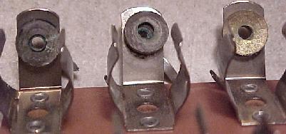
The Battery Holder: a Weak Link.
If after replacing the batteries, you still get a "Factory Setting Restored" error, suspect the battery holder. Use your DMM and check the battery voltage at the CPU board. With the game off, put your DMM on DC volts and put the black lead on ground (the grounding strap or on one of the screws holding the CPU board in place). Put the red lead on each of the CPU board's POSITIVE battery terminal SOLDER POINTS. Test each of the three batteries' positive leads individually. You should get about 1.5, 3.0, or 4.5 volts at each battery (note the batteries are additive and the first battery in the chain will give you 1.5 volts, and the last battery will give you 4.5 volts). If you don't these positive voltages, suspect damaged battery holder terminals. These corrode quite often if new batteries aren't installed religiously. Replace the battery holder and re-test to ensure proper repair.
-
The best battery holder to buy for any WPC game is the new black plastic battery
holder used in WPC-S and later games. This is Williams part# A-15814. This design
of battery holder is much better than the pre WPC-S design.
Is power getting to the U8 RAM chip?
With your game off and batteries installed, put your DDM on DC volts and
put the black lead on the backbox ground strap. Then put the red lead
on diode D2 on the CPU board. The banded side of the diode should show
about .5 volts less than the non-banded side (which should be about 4.3 volts).
If only one side of the diode shows voltage, this 1N4148 diode is bad.
Next test for voltage at the CPU U8 RAM chip. With the game off, you should get about 4.3 volts DC at pins 26, 27 or 28 of chip U8. If you don't, the battery voltage is not getting to the U8 RAM chip, and the game will boot up with the "Factory Settings Restored" error. Note pin 28 of the 28 pin U8 chip is in the same position as pin 1 of the chip, but on the opposite row of pins. Pin 1 is designated with an impressed "dot" right on the top of the chip.
You can still have problems even if you installed new batteries and all the voltages check out. If your game is still giving "Factory Setting Restored" or "Set Time and Date" errors, you may have a bad CPU U8 RAM chip. But make sure you double check that battery holder. Even minor corrosion can cause this problem. The voltages may all check out, but the corrosion may be enough to limit CURRENT, and cause this problem. The U8 RAM chip is a 6264-L or 2064 RAM chip.
-
My Game's Time Clock is Slow!
There is an internal time clock that keeps the time and date for the WPC system. Within the game's adjustments, you can turn the clock display on, so it shows the time and date on the dot matrix display. On Twilight Zone, this internal time clock is used during attack mode to set the playfield clock. If you notice the WPC time clock running slow (losing time), or the game just won't remember the time (boot up error of "Set Time and Date"), the batteries are getting weak and need replaced. If you still have this problem with new batteries, suspect the battery holder's terminals. They may be corroded enough to cause resistance, and lower the voltage at CPU chip U8.
-
Changing Batteries.
If your game is working, and it's time to replace the batteries, follow this procedure:
If you install new batteries with the game turned on, the machine will not forget the old option settings or bookkeeping totals.
3n. When things don't work: Lightning Strikes
-
All William's WPC pinball games are very durable commercial devices.
They are well protected against voltage surges from lightning storms.
There are several lines of defense against voltage surges:
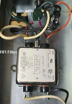
The MOV is the green disc soldered across the
lugs of the radio frequency interference filter.
-
The MOV (metal oxide varistor) is designed to have high resistance.
But when its rated voltage is exceeded, it internally shorts.
This immediately blows the line fuse and halts the power
to the game, saving everything but the line fuse and the MOV itself. Smaller
voltage surges are absorbed by the MOV without total destruction (though
lots of small surges can eventually destroy a MOV and make it short).
-
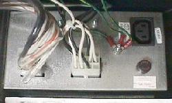
The MOV is located inside the cabinet's metal power box, next to the coin
box. If you need to replace it, here are
the values needed:
-
The rating is the voltage at which the MOV will short.
Lower voltage ratings will provide more protection. But
remember the power supply circuits have other protections from high
input voltages too. So don't select a voltage too low, or
you'll be replacing the MOV often from small voltage surges.
Radio Shack sell MOV's that
work well in WPC games.
3o. When things don't work: Sound Problems.
-
The sound on WPC games is very robust; it just doesn't fail
too often. But here are some things that do fail related to sound:
Volume up FULL and Can't turn it Down.
The volume control on all WPC games is electronic. On pre-WPC95 games, this
is controlled by an electronic prom pot. This E-pot is a X9503, at location U5 on the
sound board. If turning the volume up or down has no effect, and the volume
is stuck on full blast, this is the first component that should be checked.
Also the capacitor C18 (47 mfd, 25 volts) that connects to the E-pot can fail too, and should
be checked.
Lots of Static.
Problem sound boards can produce a large amount of static. The TL084 quad Op-Amp (U21 on WPC-S and prior)
can be the cause of this. Also the TDA2030 amp can also cause this. Finally the large filtering
1000 mfd 35 volt capacitors can also be the problem. Finally check for cracked solder joints on these 1000 mfd
caps (solder jumper wires, as done to the bridge rectifiers explained earlier).
3p. When things don't work: Test Report & The Diagnostic Dot.
-
WPC's built-in diagnostics are very good. It can determine problems with your
game long before you have even noticed them. When you power a WPC game on,
if diagnostics detects a problem, you'll get a "test report" notification message.
Pressing the "begin test" button inside the coin door will display the full test
report. Each problem will be shown on the display for a few seconds. If there's
no test report at power-on, the diagnostics thinks the game is working 100%
correct.
Most test reports refer to switches that are tagged as defective. Often this is not the case. If a switch hasn't be used in 30 games, it will be listed as bad. But it could be the switch is working, yet positioned in a place that it just doesn't get activated much during game play.
If you do get a test report about a possibly defective switch, go to the "switch edge" test and manually activate the switch. This will indicate if the switch is working. If it does work, this will reset the 30 game counter for this switch and the switch will not be reported in the test report.
Prototype ROM Software and Bad Switches.
If your game has early prototype U6 CPU EPROM software, sometimes
non-existant switches can show up in the test report. This happened
in early versions of Twilight Zone and Judge Dredd games. There is no
way to correct this but to upgrade to the lastest U6 CPU EPROM software.
A new EPROM will need to be "burned" (using an EPROM programmer).
The software for this is available at Williams' home page at the
http://www.pinball.wms.com/tech/roms.html
website.
The Diagnostic Credit Dot.
If you are checking out a game that is being operated, look for a
period after the number of credits shown on the display during
attact mode. If there is a period (dot) after the number of credits,
this means there is a test report for the game. If there is no period
after the credits, there's no diagnostic test report and the game is
probably functioning correctly.
3q. When things don't work: Fixing a Dead or non-booting CPU board.
It doesn't happen often on WPC games. You have power (+5 and +12 volts) getting to the CPU board. The +5 LED (lower of the three) is on, as it should be. But the middle diagnostic LED is not flashing constantly (indicating the CPU is dead). And the blanking LED (the top one) is doing nothing (no flashes when the game is turned on). You have a dead CPU.
WPC-S and Prior CPU Flash Codes .
D19 is labeled "blanking", D20 is labeled "diagnostic" and D21 is labeled "+5vdc".
WPC-95 CPU Flash Codes.
LED201 is labeled "blanking", LED202 is labeled "power" and LED203 is labeled "diagnostics".
Dead CPU Step One: Remove the Ribbon Cables.
Before you do anything, turn the game off and remove all the ribbon cables
from the CPU. This will issolate the CPU from the driver board, the dot
matrix display board, the sound board, the fliptronic board (if your
game has one), and any other connecting boards. The ribbon cables are
at connectors J201, J202, J211, and J204 (on some games). While you're
at it, you might as well remove the switch connectors at J205 to J209,
and J212. The only connector still attached is J210 (the power connector).
After everything is removed but connector J210, turn the game on. If the CPU board boots correctly, the lower LED (+5 volts) should be on, the middle LED (diagnostics) should be blinking continually, and the top LED (blanking) should be off. If this is the case, turn the game off and replace the ribbon cables, one at a time, and turn the game back on. When the CPU doesn't boot, you have found the connector (and hence the board) that is dragging the CPU down.
Move to the Work Bench.
If the above "step one" didn't get you anywhere, don't worry.
Now it's time to remove the CPU from the game.
Don't try and fix a dead CPU while it's still in the game. You are
much better off fixing it on your workbench. Fixing it on the workbench
means you have issolated the bad CPU from the rest of the game (including
it's power supply!).
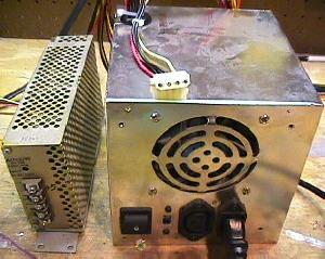
and ground are clearly marked on these.
Right: a computer power supply. You'll have to check the
power supply lines to get the right voltages on these.
But 99% of the time, red = +5 volts, yellow = +12 volts,
and black = ground. Double check them with your DMM.
-
The best power supply for your CPU is one of those switching video
game power supplies, or an old computer power supply. You need to get
+5 and +12 volts, and ground from the power supply. On computer power
supplies most of time red = +5 volts, yellow = +12 volts,
and black = ground.
J210, the green aligator clip goes to ground, the red to +5 volts, and
the yellow to +12 volts.
-
Now hook up the power supply to the CPU board using aligator clips.
Here's the pinout for the power connector J210 on the CPU board. Note
pin 1 starts at the top of connector J210:
With the CPU on the workbench and issolated from the game, you can test the board much easier.
Re-seat the U9 WPC chip.
You would be amazed at how often this works. A dead CPU
can suddenly come to life after removing and reinserting
this large U9 chip. You will need a special tool to remove this
big, square chip. You can buy this tool at Radio Shack,
part number 276-2101, $9.99. Do NOT try to remove this chip
without this tool! Note one corner of this chip is "notched",
so you can only re-insert the chip one way.
Bad socket at U9.
The large U9 WPC square chip can have a bad socket.
It's not much fun to replace this 84 pin socket!
Radio Shack sells replacement sockets, part number
RSU 11354453, $1.99, but they may not stock it.
Use your DMM and check for continuity with the chip
installed before you replace this socket.
Shotgun Approach.
The chips are U1, U2 (74LS244) and U3 (74LS245) are
the ones that affect on a dead CPU the most.
If replacing those yeilds nothing, then try replacing U5 (74LS14).
Also check resistors R95 and R99 (1 meg ohms) to make sure
these are the correct value. Finally U10 (a MC34064
transistor that is part of the startup circuit) can be replaced.
Using a logic probe, also check for a good clock signal on pins 34 and 35 of U4 (6809).
3r. When things don't work: Miscellaneous Oddities.
The Clock won't keep Time.
Problem: The internal time clock appears to be running very slow, only about 25% of realtime speed.
Numerous spot checks show that it advances about 6 hours per day. The batteries, which when weak can
cause the clock to lose time, are brand new.
The clock function is handled by U9 (the ASIC chip) and U21 (a CMOS 4584), and the 32.768KHz crystal.
Answer: Both legs of crystal X1 were soldered to the same spot! It looks like it came from the factory that way. After removing the crystal and putting both legs in the correct locations, the time is tracking correctly.
The 32.768 KHz crystal is very common and used in everything from wrist watches to computers to anything that keeps time. The reason for that particular frequency is 2 to the 15th power equals 32,768. The frequency is very easy to divide by two, fifteen times, using flip-flops or some other form of divider network. This nets a one second time increment. Since your crystal was shorted, the oscillator was free running at a RC-determined frequency that undoubtedly drifted with temperature and miniscule voltage changes, hence the accumulated errors.
I can't enter my high score initials on Funhouse.
Problem: game works fine, but won't let player advance through the initials
by pressing the flipper buttons when a high score is achieved.
The start button works correctly as "enter",
and the flippers work fine in game play.
Answer: there are two optocouplers on the power driver board at U7 and U8 that are numbered 4N25. If these go bad, they will prevent the flippers from moving through the high score initials. Since this game does not have fliptronic flippers, these optocouplers don't effect the flippers themselves. If this was a fliptronics game, the flippers wouldn't have worked either.
The flippers and dot matrix display died while playing a game.
Problem: The flippers on my Indy Jones died. The dot matrix display only has one vertical line
which is always lit. The GI lamps are fine, as are the controlled lamps.
I turned the game off and back on, the game continually launched balls
from the ball trough.
Answer: the +12 volts has died, probably from a bad fuse at F116, or maybe a bad BR5 bridge. Some dot matrix power is derived from the +12 volts, and the +12 volts also powers the optos (hence the auto ball launching problem and no flippers). If the +12 volts is good, unplug the fliptronics and sound board ribbon cable, leaving just the dot matrix display plugged in to the ribbon cable. Now see if the display clears up and you can see the error report.
Strange Error Message.
Problem: When I turn my Creature from the Black Lagoon on, I get the error
message "check switch #F6 U.R. Flipper". But this game doesn't have an
upper right flipper.
Answer: Every flipper opto board has two optos. One is wired to the lower and the other to the upper flipper switch inputs. This is true even on games with just lower flippers. If the flipper opto board has a dirty opto, you can get this error, even if your game doesn't have the flipper reported in the error message. Clean your flipper opto board optos with a Qtip. Replace the opto if the problem doesn't resolve.
Dot Matrix Display Got Blurry.
Problem: When I was playing my Twilight Zone, the dot matrix display
started to become very blurry. Within 5 minutes the display became
almost unreadable. The dots to the left and right of the active
ones started to flicker.
Answer: the ASIC chip on the CPU board was not making good contact to its socket. The ASIC chip is the large square chip on the CPU board. After removing the chip and cleaning all of its pins, and reseating the chip in the socket, the problem went away. Another thing to try is reseating the ribbon cables in their sockets.